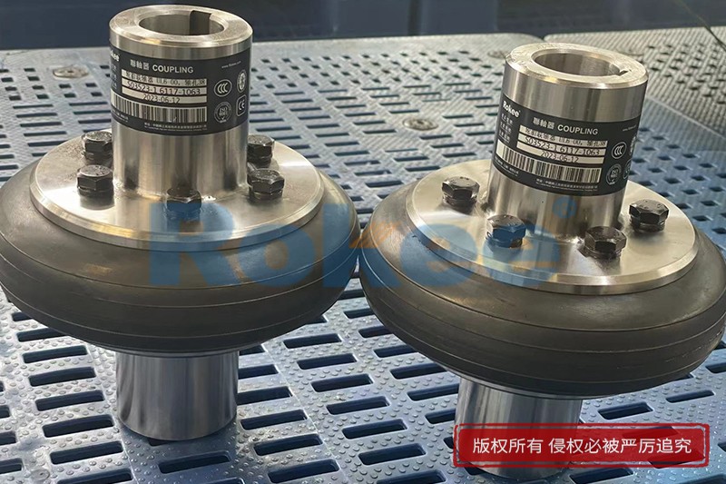
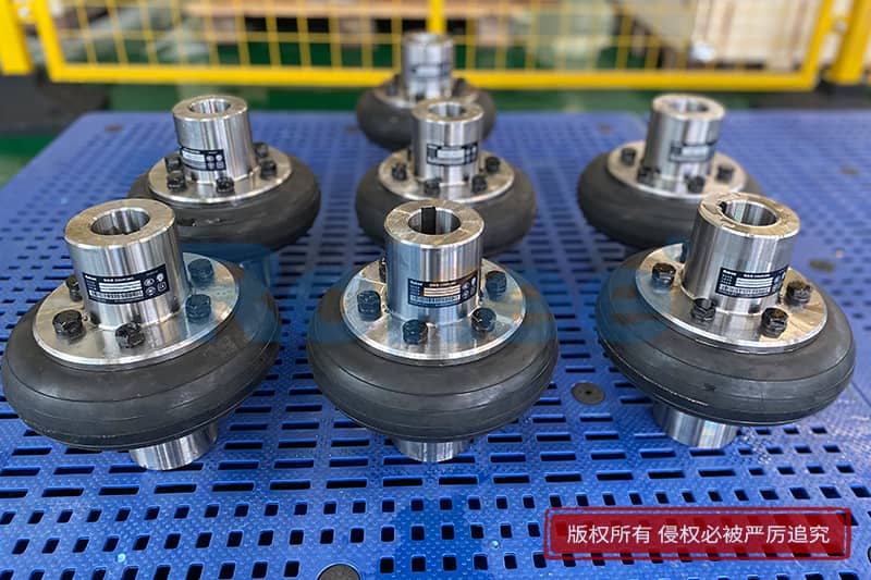
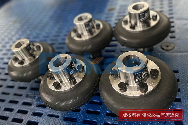
Tire Shaft Couplings Schematic Diagram
Rokee® is a well-known high-quality tire shaft coupling supplier from china, learn more about tire shaft couplings schematic diagram, pls contact Rokee technology. Rokee has been established in China since 1999, over the years, with excellent quality, we have been continuously providing many tire shaft coupling products of various categories and uses complying with multiple standards and a full range of services, from the tire shaft coupling selection to final installation and operation, for the industry fields of ferrous metallurgy, nuclear power, gas turbine, wind power, ropeway construction, lifting transportation, general equipment, etc.
The tire shaft coupling adopts tyre body-shaped rubber elements, which are connected with two semi-couplings through bolts to realize torque transmission and displacement compensation, tire shaft coupling has high elastic performance, small torsional rigidity, strong damping capacity, large axial compensation capacity, and good damping performance.
Tire Shaft Coupling Products
-
UL Elastic Tyre Coupling
UL Elastic Tyre Coupling adopts the structure of vulcanizing and bonding the tyre body with the metal connecting plate with threaded holes, which is then directly connected to the two semi-couplings by bolts for torque transmission and other displacement compensation.View More -
LLA Elastic Tyre Coupling
The LLA Elastic Tyre Coupling uses two semi-couplings to connect both sides of the elastic tyre body through internal pressing plates and bolts, making it easy to replace the elastic tyre body.View More -
LLB Elastic Tyre Coupling
The LLB Elastic Tyre Coupling is formed by fixing two halves of the coupling and the tire body together through bolts. The shaft hole type can be Y type, J1 type, and Z1 type. It has good shock absorption and excellent inter axle offset compensation performanceView More
« Tire Shaft Couplings Schematic Diagram » Post Date: 2024/5/20
URL: http://chelsea.org.cn/en/blog/tire-shaft-couplings-schematic-diagram.html
Tags: Tire Shaft Couplings ,


